NEWS CENTER
Installation and Debugging Guidance for Radar Level Meters in the Feed Industry
Huachuang measurement and control Huachuang measurement and Control Technology Co., Ltd 2025-10-31 09:22
I. Installation: Select a position within the silo where the environment is relatively stable.
1. For the installation location selection, the bottom of the tank is conical. Try to choose a position in the middle of the silo or directly below it where there are no obstructions.
2. Stay away from or avoid the reinforcing bars and the anti-breakage flow pipes.
3. Stay away from the feed inlet and ensure that the microwave beam does not intersect with the feeding material flow.
4. Make sure to install the radar only after all the electrical welding work is completed. This is to prevent the radar from being damaged by the high current of the electrical welding.
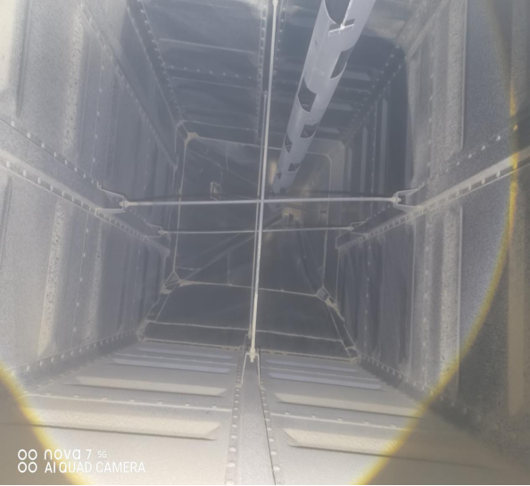
Cross-shaped reinforcing bars and anti-cracking flow pipes (the area above the red dot is the optimal installation space)
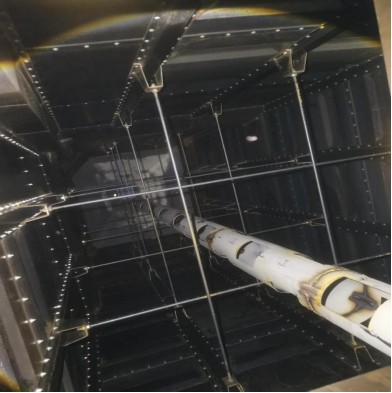
T-shaped reinforcing bars and anti-cracking flow pipes
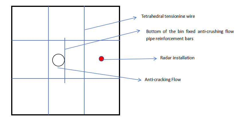
As shown in the above picture:
1.The anti-crush flow pipe is not located in the middle position. The radar installation is chosen to be on the side away from the anti-crush flow pipe.
2. The reinforcing ribs for the anti-crushing flow pipe at the bottom of the silo are parallel to the radar.
3. The installation position of the radar should not be too close to the bottom wall of the silo. Since the bottom of the silo is conical, it should be at least 0.5 meters away from the bottom wall.
II. Wiring / Connection
The wiring uses two-core shielded flexible cables of type RVVP2*1.5mm.
2. The wiring should be kept away from power cables. When parallel, the distance from the power cables should be more than 0.5 meters; when crossing, the distance should be more than 0.7 meters.
3. After connecting the lines, tighten the gland head of the inlet hole to prevent the power cables from running along the cable tray and prevent dust from entering.
Note: When connecting the radar, please follow the direction indicated on the debugging panel (generally in a counterclockwise direction) to rotate and remove the debugging panel. The connection terminals are located below the panel. After completing the wiring, reinstall the panel in the original position. Just secure it properly. Be careful not to apply excessive force, as this may damage the fixing clips or the copper sliding pins, causing damage to the radar. Currently, the radar level meters in use all have a two-wire 4-20mA output. The radar mechanism only has two connection terminals, "24V+" and "24V-". "Connect positive to positive and negative to negative".
4. The shield wire is directly connected to the internal grounding terminal, and the outside of the casing is directly connected to the earth.
III. Calibration: Calibrate the radar level gauge based on the actual on-site echo curve (When the display screen is viewed, press "ESC" to display the following echo curve)
1. Empty bin calibration: Try to ensure that the reflected signal from the bottom of the bin is the strongest, and the interference signal from the middle reinforcing bar should be as weak as possible. If the interference signal remains very strong, the installation position needs to be changed. As shown in the following figure:
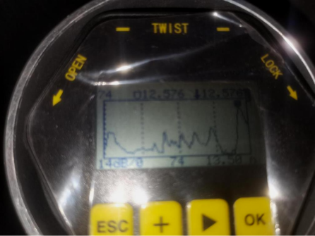
Figure 1. Weak echoes affected by the stretching force √
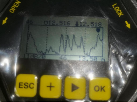
Figure 2. Echoes with strong reinforcement interference ×
The two figures above show the echo curves of two radar level meters in a certain project. The higher the peak of the wave, the stronger the echo signal. The black cursor represents the position where the radar wave is locked, which is the position with the strongest signal. The raised peak in the middle is the interference signal caused by multiple layers of reinforcing ribs. The purpose of the debugging is to make the signal strength of the actual material surface significantly higher than the interference signal (as shown in Figure 1). In this way, the cursor can firmly lock onto the actual echo with high signal strength, and the radar can perform stable measurement. Figure 2 has an interference signal and a real echo signal with similar intensities. During actual use, the instantaneous signal strength changes cause the radar to be unable to distinguish the real signal, resulting in a jump.
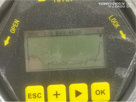
Echo curves of radar level meters without tensioning devices and anti-breakage flow pipes
2. Debugging during production: Since there will be accumulated materials on the surface of the reinforcing wire after it enters and exits the feeding system, it is necessary to check the echo curve of the radar level gauge several times after the material is fed in and out of the storage bin to see if there is any change, and then perform false echo learning debugging (in the "Professional Settings" option)
False echo learning: To eliminate the interference caused by the reinforcing ribs on the actual material surface, false echo learning is required to block the interference signals generated by the reinforcing ribs. This is especially necessary after several normal production cycles of feeding and discharging, or when there are sudden fluctuations or jumps in the data.
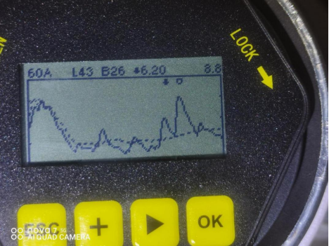
Before the false echo learning process, (the dotted line does not cover the peak of the interfering signal in the front, while the solid line does) the small black dots sometimes would seek the peak of the interfering signal from the front wire.
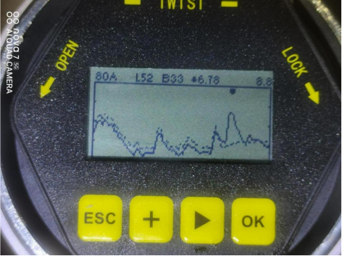
After the false echo learning process, by using the virtual lines, the interference signals of the reinforcing bars in the front were covered by the real wave peaks of the solid lines. The small black dots then search for the actual surface signals.
Note: When learning false echoes, 1. Do not conduct full-range false echo learning. Doing so will cover the actual material surface or the bottom signal of the empty bin, preventing the radar level meter from accurately measuring the material surface. 2. Learn in the space between the material surface and the radar. For example: if the bin height is 8 meters, false echo learning can be conducted from 0 to 7 meters when the bin is empty. If there is 4 meters of material inside, when there is an interference signal at 2 meters, false echo learning can be conducted from 0 to 3 meters when there is material.
If you have any needs, please contact us!
Contact number: 400-851-0898


WhatsApp +8615027566496

South of Puhui Street, west of Guangsheng East Road, High tech Zone, Fengnan District, Tangshan City, Hebei Province
Technical support:
Tips
Submitted successfully
Determine
Tips
Submitted successfully
Determine