Difficult to Monitor Furnace Bottom Wear and Material Buildup in Steelmaking Converters? Online Detection Solution Using a Special Large-Lens Frequency-Modulated Radar Level Gauge
Huachuang measurement and control Huachuang measurement and Control Technology Co., Ltd 2026-11-18 16:52
1. What high-temperature measurement blind spots and safety hazards related to refractory lining erosion at the furnace bottom do steelmaking converters face?
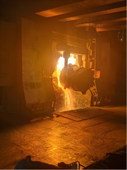
In the steel metallurgy industry, the basic oxygen furnace (BOF), as the core thermal process equipment for decarburization, dephosphorization, and refining of hot metal, operates for long periods in an extremely harsh high-temperature, multiphase-flow reaction environment. During continuous blowing, tapping, and slagging cycles, the refractory bricks lining the interior of the converter are directly subjected to severe thermal shock, chemical erosion, and high-speed mechanical scouring from molten steel and high-temperature slag above 1,600°C. Over long smelting cycles, the lining inevitably undergoes localized physical spalling and melt loss, leading to thinning. At the same time, residual slag and cold steel left after tapping can easily cool and solidify locally at the furnace bottom, forming unpredictable adhered material buildup and furnace-bottom thickening. Inaccurate monitoring of the lining condition can bring catastrophic safety risks and economic losses to steel plants. On the one hand, if wear and thinning of the furnace-bottom refractory bricks are not detected in time, they can easily trigger extremely serious major safety accidents such as severe steel leakage, furnace penetration, and explosions. On the other hand, excessive deposition and adhesion of cold slag at the furnace bottom can thicken the furnace bottom, not only reducing the effective bath volume and deteriorating the blowing dynamics flow field, but also lowering the hit rate at the smelting endpoint and increasing energy consumption. However, traditional manual visual inspection is not only inefficient but also subjective and crude in judgment, and operators must work in close proximity to intense thermal radiation, spatter sparks, and toxic and harmful dense smoke when the converter is tilted and the tapping hole is opened, posing an extremely high risk of occupational injury. Meanwhile, ordinary laser distance-measuring equipment attempted by some steel plants often suffers from severe scattering, absorption, and energy attenuation of the laser beam in the harsh environment of intense high-temperature smoke rising from the converter mouth, turbulent thermal convection, and extremely high concentrations of iron oxide dust, resulting in frequent data packet loss, measurement lockout, or even complete failure.
To completely eliminate the high-risk hazards of manual visual inspections and overcome the physical failure of optical lasers in environments with dense smoke and dust, modern steel mills must adopt microwave radar detection technology with exceptional smoke and dust penetration capability and long-range millimeter-level ranging accuracy, thereby establishing a non-contact, all-weather online monitoring system for converter bottom thickness. During the planning stage, the engineering and technical teams of steel enterprises must systematically review the harsh operating conditions at the converter front, including the converter nominal capacity and hearth depth-to-diameter ratio, the positioning accuracy of the converter tilting mechanical drive, the high-temperature radiative heat flux density at the furnace mouth, the physical installation spacing and seismic requirements of the front-end detection brackets, and the data linkage logic of the metallurgical automation control system. Deeply integrating a high-temperature-resistant microwave focusing large-dish antenna, a high-frequency frequency-modulated continuous-wave (FMCW) radar echo ranging algorithm, a high-precision optical calibration aiming system, and the PLC control program for converter tilting is the fundamental technical path to accurately quantify the erosion of converter bottom refractory bricks and the thickness of cold slag adhesion, prevent converter bottom penetration accidents, and optimize the relining cycle.
II. How does the HCDAR-9X special large lens frequency-modulated continuous wave radar from Huachuang Measurement & Control precisely achieve online thickness measurement at the bottom of the furnace?
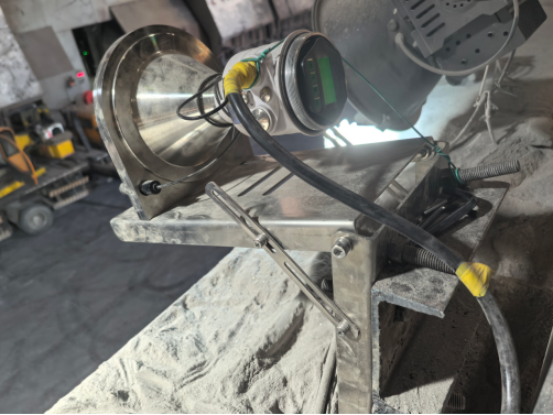
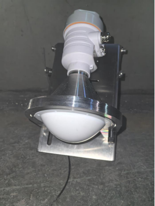
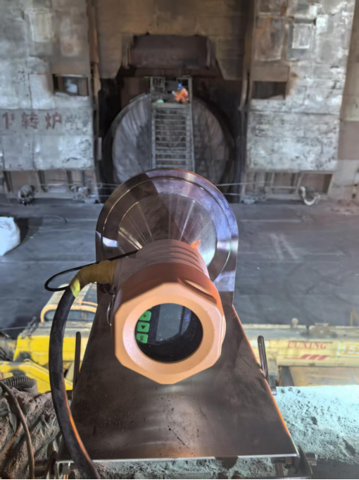
For extreme working conditions such as high-temperature baking of large steel-making converters, thick smoke, dust flying, and ultra-long distance measurement, Huachuang Measurement & Control has specially developed the HCDAR-9X series of special large lens frequency-modulated continuous wave radar level meters for metallurgical steel-making sites. This system innovatively adopts a special high-temperature-resistant medium large lens focusing antenna, which can highly converge the emitted high-frequency microwave energy into an extremely narrow spatial emission beam. Since the wavelength of the microwave is much longer than the physical size of the suspended smoke and micrometer-sized dust particles in the site, the radar's emitted high-frequency frequency-modulated continuous wave (FMCW) signal can completely be immune to the high-temperature hot smoke, water vapor, and intense dust scattering at the furnace mouth's rolling. In a non-contact state, it can directly reach the refractory layer surface of the furnace bottom at the speed of light and capture the weak surface reflection echoes efficiently. The built-in high-performance signal processor precisely analyzes the frequency difference between the transmitted signal and the reflected echo in nanosecond-level accuracy, enabling millimeter-level high-precision spatial distance measurement at a safety viewing distance of several tens of meters.
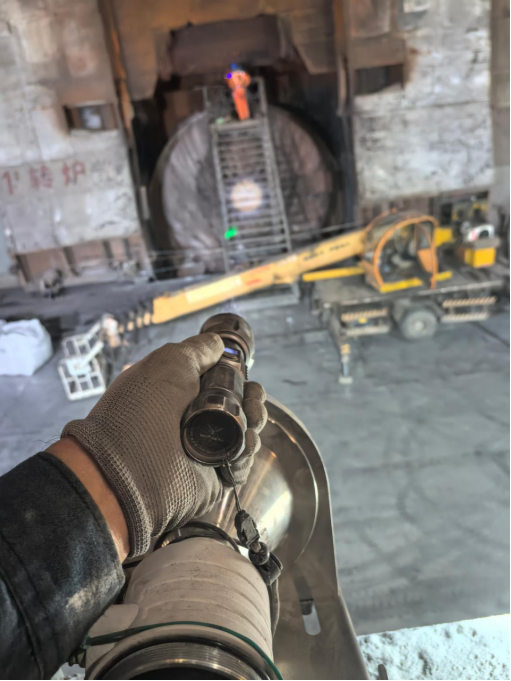
In actual industrial operation, Huachuang Measurement & Control's HCDAR-9X has established a safe and efficient non-contact online thickness measurement mechanism: The radar equipment is rigidly installed on a safe operation platform 2 meters or more away from the front of the steel-making converter, avoiding the core danger zone of molten steel splashing; during the emptying period after the converter finishes pouring and slag removal, the converter rotates to a specific calibration angle (such as the 83° inclination calibrated precisely on-site and completed with the assistance of a dedicated high-brightness green light calibration pen for physical optical axis auxiliary aiming) at the preset control program. At this time, the feed-in opening of the converter is directly facing the radar level antenna. The radar instantly emits microwaves and accurately determines the absolute spatial distance from the antenna to the geometric center of the furnace bottom, and uses the normal reference distance from the new cold-fired furnace lining to the radar antenna (such as 28.00 meters) as the thickness evaluation benchmark:
Furnace bottom refractory brick wear and erosion warning (measured distance > 28.00 meters): When the radar measured distance is greater than the reference value of 28.00 meters (such as 28.15 meters), the system accurately calculates that the refractory brick at the furnace bottom has suffered 150 millimeters of physical erosion and thinning, and immediately triggers a furnace lining wear warning signal, alerting the central control to arrange fixed-point spraying or furnace protection operations to prevent major accidents such as leakage of molten steel through the furnace;
Furnace bottom cold slag and material accumulation thickness warning (measured distance < 28.00 meters): When the radar measured distance is less than the reference value of 28.00 meters (such as 27.80 meters), it indicates that 200 millimeters of residual molten steel slag have accumulated on the furnace bottom surface, and the furnace bottom has significantly thickened. The system automatically prompts the operator to adjust the slag removal and furnace protection process or take mechanical/thermal slag removal measures to quickly restore the rated effective volume of the converter. In addition, HCDAR-9X is equipped with a heavy-duty water-cooled/fan-cooled heat insulation shell and a continuous compressed air blowing system, supporting 4–20mA, RS485 Modbus, and industrial Ethernet protocols. Each time the converter is shaken, the distance and thickness change curve of the furnace bottom is uploaded in real time to the steel converter steelmaking automation DCS and Huachuang Cloud platform, building a digital twin archive of the furnace bottom refractory life throughout the furnace service period.
III. Installation Specifications for Converter Furnace Front Engineering, Optical Axis Calibration, and Essential Parameters for Customer Selection
When deploying the Huachuang Measurement and Control HCDAR-9X special large lens radar detection system at the steelmaking workshop site, strictly adhering to mechanical installation specifications and high-precision optical axis calibration procedures is the core for ensuring the long-term reliability of the data. First, the front installation bracket must have extremely high mechanical rigidity and anti-vibration performance, and the installation position must be in a safe viewing channel outside the radius of the converter's feed rotation. This ensures that the radar large lens antenna end face can be unobstructedly view the 83° inclined converter furnace opening without interference, and completely avoids the movement interference of the bag hoisting crane and the feeding machine arm. Before the equipment is put into operation, the matching high-brightness green light calibration pen must be assembled in the coaxial calibration hole of the radar, and when the converter rotates to the position, turn on the green light to aim at the light spot, fine-tune the two-way universal joint base of the radar to ensure that the microwave radiation optical axis precisely falls within the geometric center area of the converter furnace bottom. In terms of environmental protection, it is necessary to connect a constant-pressure clean compressed air to continuously and continuously blow the surface of the large lens, preventing the secondary deposition and coking of high-temperature smoke dust; at the same time, connect the water-cooled heat insulation sleeve ring to stabilize the working temperature of the radar core electronic components within the safe threshold.
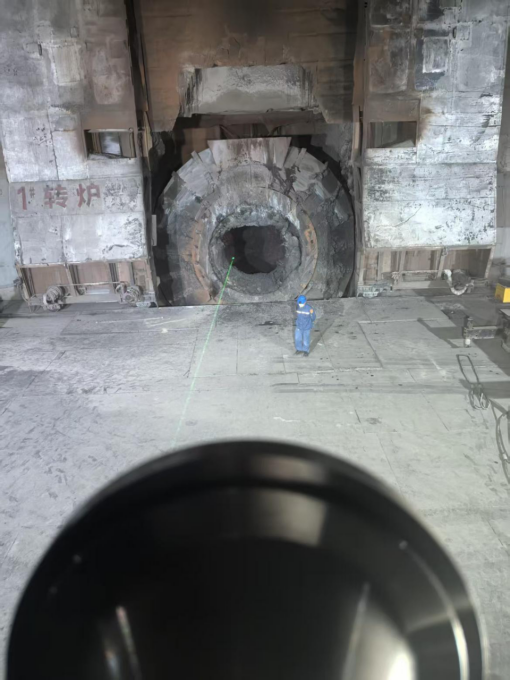
During the system debugging phase, the technicians set up the trigger logic for collecting the tilt angle of the converter in the central control software. That is, the system will automatically start the high-frequency ranging and record the effective filtered peak value only when the feedback tilt angle of the converter from the encoder is stable at 83° during the maintenance window period and the furnace opening is facing the radar directly. When steel enterprises consult the Huachuang Measurement and Control Technology Team about the converter radar detection system solution, they are advised to prepare and provide the following on-site basic operating condition data:
Converter body specifications and spatial geometric parameters: nominal tonnage of the converter (such as 80t, 120t, 150t, 250t, etc.), inner diameter of the converter opening, total depth of the furnace chamber, elevation of the rotating center of the converter, and the straight-line distance from the front of the converter to the furnace opening available for installation of the support;
Converter operation and calibration angle parameters: rated positioning angle of the converter during maintenance/thickness measurement (such as 83° or the recommended angle at the site), positioning repeatability accuracy and the allowable time window for each thickness measurement (usually 10 seconds to several minutes);
Refractory materials and smelting process parameters: initial design thickness of the furnace bottom refractory brick, ultimate safe wear thickness, steel and slag discharge temperatures, and material of the furnace bottom spalling;
Public engineering and control system interface: on-site pressure parameters of compressed air source and water temperature and water pressure, required electrical output interfaces (4–20mA/HART, RS485 Modbus-RTU, industrial Ethernet, etc.) and whether to need to automatically generate a furnace bottom thickness report by interlocking with the converter tilt angle PLC. The senior metallurgical instrument engineer of Huachuang Measurement and Control will customize the layout diagram of the front light path survey, the selection and configuration of the radar-specific large lens, and the complete digital monitoring system solution for the furnace lining for you.
If you are interested in the technical solutions or products described in this article, please feel free to contact us to obtain detailed product information, selection advice and technical support.
Official website: https://hhcck.com
24-hour consultation hotline: 1993137827